Sunday 13 August 2023

How do you decide best Floorplan in Physical Design?

 Designing the best floorplan in physical design is a crucial step in integrated circuit (IC) design, as it can significantly impact the overall performance, power consumption, and manufacturability of the chip. A floorplan determines the placement of various functional blocks, standard cells, and other components on the chip's silicon area. Here are the key considerations and steps involved in deciding the best floorplan:

1. Block Placement:

   - Identify the different functional blocks, such as CPUs, memory, I/O, and custom blocks, that need to be placed on the chip.

   - Consider the block sizes, aspect ratios, and power/thermal requirements of each block.

2. Hierarchy and Partitioning:

   - Determine if a hierarchical floorplan is necessary, where blocks are grouped and placed at different levels of the hierarchy.

   - Partition the design into logical regions or modules based on functional requirements.

3. Power and Signal Integrity:

   - Place power-hungry blocks and components near the power supply to minimize voltage drop.

   - Place critical blocks closer to I/O interfaces to reduce signal propagation delays and ensure signal integrity.

4. Clock Tree:

   - Plan the clock tree distribution network and place clock sources (oscillators, PLLs) strategically to minimize clock skew and power consumption.

5. Noise and Interference:

   - Consider minimizing the coupling of noisy blocks (e.g., clock generators) with sensitive analog or RF blocks.

   - Place noisy or high-frequency blocks away from critical signal paths to avoid interference.

6. Routing and Wirelength:

   - Plan the floorplan to minimize wirelength between blocks, which reduces signal delay and power consumption.

   - Arrange blocks such that the interconnects between them are short and manageable.

7. Heat Dissipation:

   - Distribute heat-generating blocks to avoid localized hotspots. Place power-hungry blocks near heat sinks or cooling mechanisms.

8. Symmetry and Regularity:

   - Use symmetry and regularity in floorplan design to simplify routing and achieve balanced performance across different regions.

9. Design Rules and DRC:

   - Adhere to design rules and design rule checks (DRC) to ensure manufacturability. Place blocks considering metal pitch, spacing, and other lithographic constraints.

10. Iterative Refinement:

    - Floorplanning is often an iterative process. Use floorplanning tools to experiment with different arrangements and assess the impact on performance metrics.

11. Tool-Driven Optimization:

    - Utilize advanced floorplanning tools that employ optimization algorithms to automatically generate or refine floorplans based on specified objectives.

12. Trade-offs and Metrics:

    - Define design objectives and metrics such as performance, power, area, and signal integrity. Make trade-offs between these metrics to achieve the best compromise.

13. Consulting Experts:

    - Collaborate with experienced physical design engineers, as their insights can help you make informed decisions based on the specifics of the design.
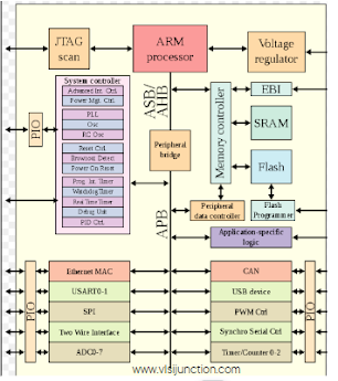


System on Chip (SoC)

A System on Chip (SoC) in VLSI (Very Large Scale Integration) design refers to the integration of multiple functional components or subsystems of an electronic system onto a single integrated circuit (IC) chip. SoC design aims to consolidate various hardware and sometimes software elements that traditionally existed as separate chips or components onto a single chip, resulting in reduced size, cost, and power consumption, while often enhancing performance and integration.

Key characteristics and aspects of SoC VLSI design include:

1. Integration of Functional Blocks: SoCs integrate different functional blocks such as processors (CPU, GPU, DSP), memory subsystems, I/O interfaces, digital and analog peripherals, communication interfaces (Wi-Fi, Bluetooth, Ethernet), and more.

2. Complexity:  SoCs are highly complex and may involve billions of transistors due to the integration of diverse functionalities.

3. Interconnect Fabric: A sophisticated interconnect fabric is required to enable communication between the various components on the chip.

4. Power Management: SoCs typically employ advanced power management techniques to optimize energy consumption by selectively powering down or adjusting voltage/frequency of different blocks.

5. Design Hierarchy: SoC design often follows a hierarchical approach, with subsystems designed and verified separately before integrating them into the final chip.

6. Verification and Validation: Due to the complexity, verification and validation of a SoC design is a significant challenge, involving simulation, emulation, and formal methods.

7. IP Cores and Reuse: SoC design often involves using pre-designed intellectual property (IP) cores for standard functions, which allows for faster development and reduces design risk.

8. Embedded Software: SoCs typically include embedded software to control and manage the hardware components, necessitating a close synergy between hardware and software design.

9.  Application Areas: SoCs find applications in a wide range of fields, including consumer electronics (smartphones, tablets), automotive (infotainment systems, autonomous driving), industrial automation, IoT devices, medical devices, and more.

10.  Design Challenges: SoC VLSI design comes with challenges like ensuring proper timing, signal integrity, thermal management, power delivery, and addressing the trade-offs between performance, power consumption, and area.

11. Customization: Some SoCs are designed for specific applications and can be customized to meet the unique requirements of that application.

12.  Advances in Technology: As semiconductor manufacturing technology advances, SoCs become more powerful and energy-efficient, enabling the development of increasingly sophisticated and capable devices.


Fig :: Example of SoC